The term “3D Modeling” refers to a process of using special software to create a 3D digital representation of an object or surface. 3D models are made for a variety of different purposes including movies, video games, architecture, and engineering. 3D modeling is also an important part of our work at CrossComm creating virtual reality (VR) and augmented reality (AR) experiences.
The Basics of Working with 3D Models in Unity
We commonly create virtual reality scenes by building or acquiring 3D models and importing them into Unity—a 3D game engine. When constructing scenes in Unity, each component that is viewed by the user has a certain hierarchy that assets in a computer graphics pipeline follow. They are:
Meshes - the actual geometry
Textures - bitmap images
Materials - how a surface should look (i.e., reflective or matte and where textures are linked to). This is also the area which shaders are applied to.
Shaders - the actual calculations that take place. Think of this as a little program (script) that helps take all the input items such as textures, meshes, and lighting data and outputs them as a final image
To further explain each of these components, let’s look at some examples from a virtual smart home experience that we created for one of the largest electric companies in the country. In this VR experience (and its companion AR experience), consumers learn how to reduce their carbon footprint by making energy efficient changes throughout the home.
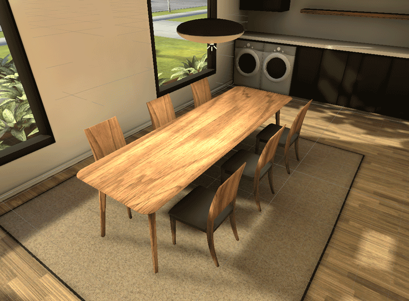
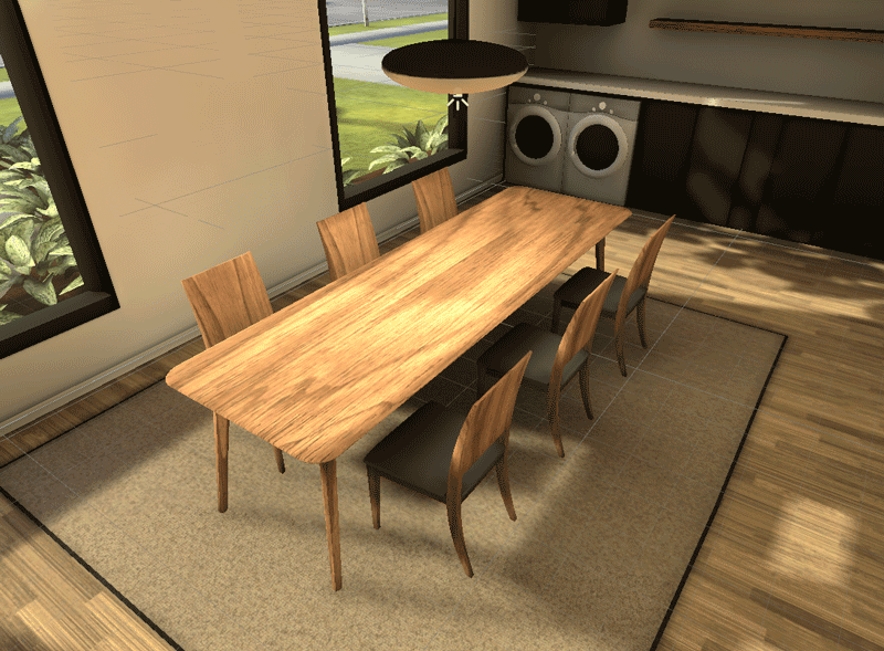
The main model we’ll be looking at is the dining room set pictured below. The final render is an example of all four components (mesh, texture, material, and shader) working together. Now let’s break down each component.
Final render from inside of Unity
Part 1 - The Mesh
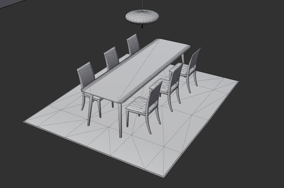
First is the model or mesh. This part is easy enough to understand. A 3D artist will create this in a modeling program of their choice. (We at CrossComm use Blender, but others such as Maya, 3DS Max or C4D are perfectly appropriate as well.) A 3D model is made up of numerous vertices which make up polygons that give a 3D model its shape. More polygons can help make the model more realistic, but too many can also negatively affect the performance on the platform that you're developing for.
Given that this is being created for real time applications, the poly count should be kept as low as possible to help maximize the performance. This is especially important for both desktop and mobile VR, as keeping a steady frame rate is paramount when it comes to crafting engaging VR experiences. This also helps reduce the feeling of motion sickness which some people may experience.
Once the model is complete, it is UV'd (more on that in the next section), exported from the modeling program, and imported into Unity.
Wireframe of a model showing topology
Part 2 - Textures
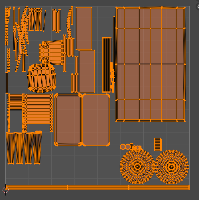
Before we go further, let's take a step back. Once the model is created, it has to be UV unwrapped. This is simply the process of taking a 3D object’s surfaces, and laying them out in a 2D space.
UV layout inside of Blender
From here, you can bring the model into a texturing program like Substance Painter to create your textures. The benefit of using a program like Substance Painter is it allows you to export various images that will later be useful when setting up materials in Unity. These images make it easier to adhere to Physically Based Rendering (or PBR), a workflow used to create more accurate renders.
For a standard PBR workflow, there are 4 main components: Albedo (base color), roughness (how shiny), metallic (is it a metallic object or not), and normal map (faking detail without adding more geometry). Additionally, there are other images you can use such as ambient occlusion (a way to simulate shadows between objects—especially noticeable in corners and other tightly packed areas), emission and height.
Breakdown of different maps used for a PBR material
Part 3 - Materials
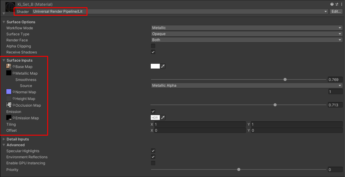
Back in Unity, after we export our different images from the texturing program, it's time to hook them up to a material. These are illustrated in the below screenshot. Additionally, you can change the surface type from opaque to transparent if you plan on using transparency in your textures. A good example of this would be if you were making plants for games. Instead of modeling the individual leaves, you could simply use a plane and apply a texture of a leaf with alpha or transparency.
Some inputs for a material inside of Unity and the URP/lit shader
Part 4 - Shader
The above screenshot also shows the final part of the equation—which shader to use. For any material in Unity, you can specify which shader to use (i.e., which algorithm or program to use to generate our final graphics). For our dining room scene, we used the Universal Render Pipeline/lit which uses all the inputs of a PBR pipeline that were described in the last section.
To take this a step further, you could even create your own shaders with a new feature in Unity called Shader Graph! With Shader Graph, instead of having to know how to code, a user can visually construct the same logic on the fly by placing pre-defined bits of code called nodes. This is helpful if you want to construct a specific shader for a specific use case. Below are two such examples.
Example 1
In the clean energy smart home experience, we needed to simulate a burger patty cooking on an induction stovetop.. For this module, the user is tasked with placing a burger on a stove to demonstrate the characteristics of an induction stove top and show how it only cooks food that is on a pan. To complete this, a 3D model of half a frying pan was needed, along with a custom shader to simulate this transition.
Example of a shader demonstrating cooking a patty on an induction stove
Example 2
A design element we included in the clean energy smart home experience was having holograms fade in and out at certain moments to help illustrate certain concepts. To achieve this, we again needed a custom effect. In an effort of brevity, the below dissolve effect is a combination of various nodes that create a black and white mask which drives the alpha transparency threshold of the shader.
Example of hologram shader
We used this workflow of model creation, textures, and shaders to build all the modules and environments found in the clean energy smart home experience. Some of the modules in the house consisted of:
An electric vehicle module where the effects of regular internal combustion cars are compared against the benefits of electric vehicles
An HVAC module where the user can observe the effects that air leaks in a house can have on energy efficiency.
An induction stove module where the cost savings and carbon emissions of induction and traditional gas powered stoves are compared
There is much more to consider and learn when creating or working with 3D models—this article barely scratches the surface. However, understanding how meshes, textures, materials and shaders work together is a great way to start grasping what is necessary to create realistic 3D objects and surfaces. In the case of this project, we built an experience that allowed users to engage with learning modules in an energy efficient, virtual smart home. But mastering those same four components can empower a designer to create an unimaginable number of dynamic, 3D scenes that can dazzle and immerse users.
